Yes -
Wiring question
I use mine for the aux. fuel transfer pump, one for each axillary tank and front mounted fog lights.
I still have a position to add one more accessory in the future. Just think of it as a five position switch

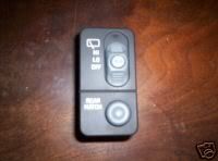
The Crew Cabs received the wiring of the utility (Blazer) not the pickup. So We do have the wiring for the hatch release and rear wiper controls.
Heres the available wiring:
Pin A YEL = Accessory Voltage
Pin B DK GRN = Rear Window washer Control
Pin C GRY = Rear Window Wiper Switch Signal
Pin D BLK = Trunk Release Switch Signal
Pin E BLK = Ground
Pin F GRY Instrument Panel Lamp Fuse Supply Voltage
I installed some LEDs since the picture you posted above. Two yellow and a green. One for each fuel tank and one for the fog lights.

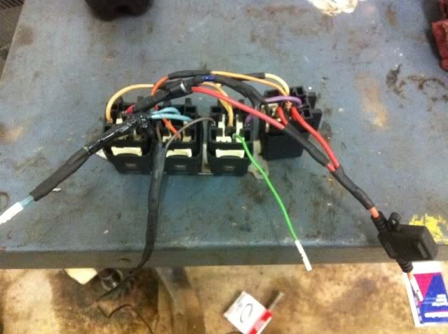
I used the YEL for my switch to supply, small GRY dash lights, Green for push to supply, BLK for ground, then added a couple wires of my own for wiring to the relays.
Modding the wiper / hatch release switch
I used three
1/8" 12 volt LED's from Painless wiring Here is another source for 12 volt LED indicator lights -
Streetworks
I did modify the internal lighting of the switch by removing part of the optical plastic that lights the left portion of the switch plate. and sanded the pictogram off the washer button.
The left side did not turn out as I would have liked, so I just put some opaque vinyl over it and installed the LED's.
The LED's are just a press fit. Drill the holes and push them in.
The upper yellow LED lights when my front aux. fog lights are on. The green LED lights while holding the momentary switch for the fuel transfer pump as does another yellow I mounted next to it for the other fuel transfer tank.
Here are some quick shots of what to do:
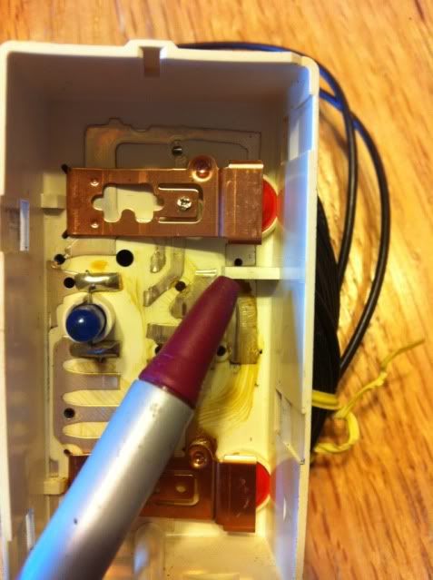
Disassemble the switch. Just push in the four grey hooks that hold the face to the white back to release.

Then pull the clear plastic piece out

You will need to cut off the top and bottom parts (sorry for some of the blurry pics, I was doing this in a hurry)

I used two coats of primer on the inside , drilled one of the 5/32" holes for a LED, then painted the primer black.

Of course for the finished product I would paint the entire piece to match the dash and cover up the lettering on the front.
Push the LED into place and drill a 5/32" hole in the side of the back for the wires to exit.

Put all the pieces back in place. Push the wires through the hole.

Snap it back together.

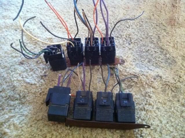
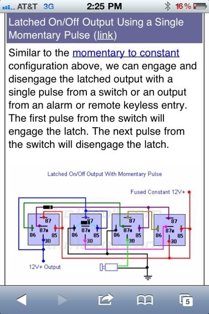
You will need to install a relay. Here is a diagram:

#85 , green positive relay activate
#86 , black negative relay activate
#30 , yellow supply
#87 , white Normally open to accessory
#87a , black Normally closed to accessory
To get the wires into the engine compartment you can go through the rubber boot on the bundle that comes through the drivers side firewall , between the fender and brake booster.

To do this remove the lower dash panel that includes the OBDII port, above the drivers footwell. You will need a long piece of rod. I use gas welding rod, or fluxless brazing rod. A straightened metal coat hanger may work well too.
Poke it through the rubber boot from the engine compartment piercing through to the inner seal and into the footwell. If the rod is thin like the welding rod I bend the end back in itself and insert the stripped end of a wire through the tightened loop. The tape it tightly and pull it back through to the engine compartment. The next time will be easy as the rod will follow the wire back through.
For powering the lights you will need to
add an accessory power source. Energizing the fused accessory power stud in the engine compartment power distribution center-

...is as simple as adding a maxi fuse and 6mm-1.00 nut. For terminal ends a 1/4" hole should work-

This is a handy place to provide power for added accessories.
Be sure to check the sticky ,
Cable Gauge Selection Chart ( Wire size table ) , in this forum for the proper sized wiring.
